- Scope:
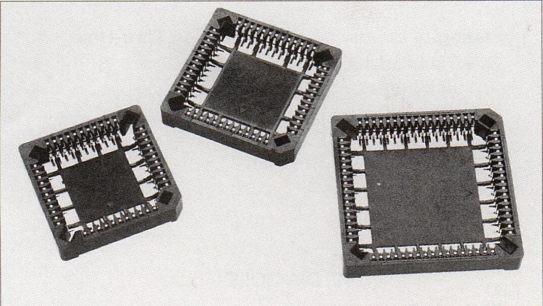
This PLCC (plastic leaded chip carrier) sockets are designed to carry JEDEC Type A
chips on 1.27 mm (0.050in.) centerlines. It is available in surface-mount configurations
of :
20 pin positions.
28 pin positions.
32 pin positions.
44 pin positions.
52 pin positions.
68 pin positions.
84 pin positions.
The socket’s low-profile design minimizes overall height. And high temperature
plastic suitable for all SMT soldering processes.
- Applicable Specifications:
The following documents form a part of this specification to the extent specified
herein. In the event of conflict between the requirements of this specification and the
product drawing, the product drawing shall take precedence. In the event of conflict
between the requirements of this specification and the referenced documents, this
specification shall take precedence.
MIL-STD-202F Test methods for electronic and electrical component parts.
MIL-STD-1344A Test methods for electronic connector.
UL 94 Flammability standard.
MIL-T-10727 Tin plating standard.
FED-QQ-N-290 Nickel plating standard..
FED-QQ-B-750 Phosphor bronze standard.
- Requirements:
3-1 Design and construction: Product shall be of the design, construction and
physical dimensions specified in the applicable product drawing.
3-2 Materials:
3-2.1 Housing: Polyphenylene sulfide UL-94V-0. Color: BROWN.
3-2.2 Contact: Phosphor bronze.
3-3 Finishes: Selected Tin 150m "(3.75m m) minimum on solder tail area, and selective Nickel 50m "(1.27m m) minimum overall.
3-4 Ratings:
3-4.1 Voltage rating: 120V AC.
3-4.2 Current rating: 1A max.
3-4.3 Operating Temperature: -55ş C to +105ş C
3-5 Product Dimension: Ref. Customer drawing.
4.Quality Assurance Provisions
4-1 Test specimens shall be inspected to assure compliance to the requirements of
this specification.
4-2 No sample shall be reused unless otherwise specified.
5.Packaging:
Parts shall be packaged tubes or tape&reel.
6.Supplementary Information:
The recommended PCB layout as shown on customer drawing are not to be used for the
acceptance nor rejection of the part herein.
7.Test Requirements And Procedures Summary:
Para. |
Test Items |
Requirements |
Procedures |
Mechanical Requirements |
7-1 |
Contact Retention Force |
0.3 Kg MIN. (per pin) |
Apply axial push force at the speed rate of
25mm/minute. MIL-STD-1344A,method 2007.1 |
| Result: Contact
Resistance unit: Kg |
MAX. |
MIN. |
AVE. |
| 0.9 |
0.6 |
0.8 |
7-2 |
Solderability |
Solderable area shall have a solder coverage of
95 % minimum. |
After 5-10 sec flux deep. Subject connector lead
to solder both (63% Sn / 37% Pb) at 230 ±5°
C for 5±0.5 seconds MIL-STD-202F, method 208E |
| Result: Over 95% coverage on solder tail. |
7-3 |
Resistance to Soldering Heat |
No evidence of defects on surface. |
to solder at 260 ±5° C for 5±0.5 seconds, no evidence of
distortion of plastic or metal components or any other damage when examined under 3X
magnification. MIL-STD-202F, method 210A |
| Result: No damage. |
7-4 |
Insertion Force |
Used gauge of MAX.: 6.0 KG MAX. Used gauge of
MIN.: 1.5 KG MAX. |
Subject mated applicable gauge (MAX.
and MIN.) Operation speed shall be 25~100 mm/minute. MIL-STD-1344A,method 2013.1 |
| Result: MAX. MIN. AVE. unit:
Kg I. MAX. GAUGE 4.2 3.5 3.8
II. MIN. GAUGE 1.3 1.2 1.3 |
7-5 |
Withdrawal Force |
Used gauge of MAX.: 3.5 KG MIN. Used gauge of
MIN.: 0.8 KG MIN. |
Subject mated applicable gauge (MAX. and MIN.)
Operation speed shall be 25~100 mm/minute. MIL-STD-1344A,method 2013.1 |
| Result: MAX. MIN. AVE. unit:
Kg I. MAX. GAUGE 3.7 3.6 3.6
II. MIN. GAUGE 1.9 1.0 1.1 |
7-6 |
Durability |
Used gauge of MAX.: 10 times or
Used gauge of MIN.: 20 times
Contact Resistance less than twice of initial.
No physical damage. |
Subject mated applicable gauge (MAX. or MIN.)
Operation speed shall be 25~100 mm/minute.
MIL-STD-1344A,method 2006 |
| Result: Contact Resistance MAX.
MIN. AVE. unit: milliohms 25.8 16.9 22.8
No physical damage. |
7-7 |
Vibration |
Contact Resistance less than twice of initial. No
physical damage.
|
Mated applicable gauge and Subject to the
following vibration conditions, for a period of 2 hours in each of 3 mutually
perpendicular axes, passing DC 1mA during the test. Amplitude: 1.5mm P-P.
Frequency: 10-55-10 Hz.
MIL-STD-1344A,method 2005.1 condition I |
| Result: Contact Resistance MAX.
MIN. AVE. unit: milliohms 28.6 19.9 25.6
No physical damage. |
Electrical Requirements |
7-8 |
Contact Resistance
(Low Level) |
30 milliohms MAX. |
Subject mated applicable I.C. and
measure by dry circuit, of 100 mA MAX. 20mV . MIL-STD-1344A-method 3002.1 |
| Result: |
MAX. |
MIN. |
AVE. |
| unit: milliohms |
13.0 |
6.7 |
8.7 |
7-9 |
Insulation Resistance |
1000 megaohms min. |
Apply 500 V DC test potential across
contacts, and contacts to housing. MIL-STD-1344A-method 3003.1 |
| Result: Insulation resistance 1000
megaohms min. |
7-10 |
Dielectric Strength |
Connector must withstand test potential of 600
VAC (RMS) for 1 minute. No evidence of flashover or breakdown. |
Measure by applying test potential
between the contacts, and contacts to housing. MIL STD-1344A-method 3001.1 |
| Result: No evidence of flash-over
or breakdown. |
Environments Requirements |
7-11 |
Salt Spray |
Contact Resistance less than twice of
initial. 30 milliohms MAX. |
Subject mated applicable connectors
to 5% salt concentration , 35± 1°
C temperature, 95-98% humidity for 48 hours. MIL-STD-202F,method 101D condition B |
| Result: Contact
Resistance unit: milliohms |
MAX. |
MIN. |
AVE. |
| 24.2 |
20.5 |
21.6 |
7-12 |
Humidity |
Contact Resistance less than twice of initial. 30
milliohms MAX.
Dielectric Strength no damage. |
Subject mated applicable connectors
to 40± 2° C temperature, 90-95%
humidity for 96 hours. taken within 30 minute after tested. MIL-STD-1344A,method
1002.2 condition B (Type I) |
| Result: Contact
Resistance unit: milliohms |
MAX. |
MIN. |
AVE. |
| 24.1 |
22.1 |
24.3 |
| Dielectric Strength (After Test)
no damage. |